Genial Joysticks (C) Copyright
1983-2003 Simon N Goodwin
First Published in Digital and Micro Electronics, Autumn 1983
Scanned by Andrew Hague & updated by the author, January 2003
Adapted to HTML by Knut Roll-Lund, September 2003
A switched joystick can easily be added to a Genie computer (or to
other popular micros), to duplicate a feature of far more expensive
systems.
Have you ever wished you could use arcade-style joysticks to play games
or edit data on your computer? This article explains how you can alter
a Video Genie to accept input from standard joysticks. The modification
can be carried out in about an hour, at a cost of £6-7, and if
you build your own joystick mechanism the cost could be less than a
pound!
This simple hardware modification gives you the convenience of being
able to steer items around the screen in the currently fashionable way.
You could even add a home-made 'mouse' to your computer, similar to the
one used on Apple's kilopound 'Lisa' system. Another advantage is that
a joystick reduces keyboard wear and tear - frantic button-pressing has
caused many a computer keyboard to fail!
Joystick In Action
Many programs for the Video Genie accept input from four cursor-keys
(on early Genie machines these are confusingly labelled Esc, Ctrl,
Backspace and Tab), and this project means that a joystick can be used
whenever the cursor keys are normally required. The stick's 'fire'
button will duplicate the space-bar, which is generally used to fire
shots in computer games.
Once the modification has been carried out it is possible to move the
cursor around in programs such as Scripsit (the word-processor upon
which this article was written) and Visicalc, so this project is useful
not only to games-players!
The joystick does not disable the keyboard, so that all of the keys may
still be used while it is connected. The modification has been tried
and tested for over a year on the author's machine. It has also been
successfully adapted for other computers such as the TRS-80 and ZX
Spectrum; this article will describe only the Genie modification in
detail, although the principle will be described for those who wish to
adapt other computers.
Lateral Thinking
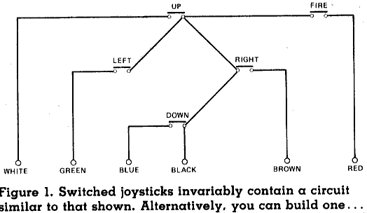
A joystick is really nothing more than a set of switches arranged in a
cross pattern, with an additional 'fire' button. Figure 1 illustrates
the internal circuit of such a stick: as you move the joystick a
plastic arm pushes one or more of the internal switches.
When you play a game using the computer's keyboard you are effectively
throwing switches to control your laser base, gunsight or whatever. The
Video Genie keyboard consists of switches in a 'matrix', as shown in
Figure 2.
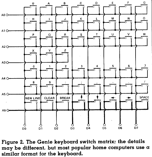
The computer can present a voltage to any of the wires on the left of
the diagram (A0-A6), and it is able to sense whether or not the voltage
has made its way to the bottom row of terminals (D0-D7). If no key is
pressed, then the horizontal wires will be isolated from the vertical
ones, and consequently the Computer will not sense a voltage.
However, consider what happens if the top horizontal Wire is supplied
with electricity and the '@' key is pressed: current will flow through
the switch to the 'D0' line at the bottom of the diagram. Likewise, if
the 'C' key is pressed current will flow to the 'D3' line. Every key in
the top row connects to a different line at the bottom of the diagram,
so that the computer receives a different signal for each combination
of keys pressed.
Whenever the computer needs to read the keyboard it merely connects a
voltage to each horizontal row of keys in turn. As it tests a row it
also reads the voltages at 'D0' to 'D7', and in this way it can test to
find out whether or not each key is pressed. If the 'Break' key is
pressed, for example, a voltage will arrive at line 'D2' when the
botton row ('A6') is energised.
Joysticks From BASIC
Program 1 shows how the BASIC PEEK statement can be used to read keys.
The internal design of the Genie means that if you PEEK address 14400
the computer sends a voltage to the bottom row of the keyboard matrix.
If no key is pressed the value returned by PEEK(14400) will be zero,
since no electricity can make its way from the row to the columns.
Program 1. Joystick Test Routine
90 CLS
100 LET P=PEEK(14400)
110 IF P AND 128 THEN PRINT @156,"BANG!" ELSE PRINT @156," "
120 IF P AND 32 THEN PRINT @147,"LEFT" ELSE PRINT @147," "
130 IF P AND 64 THEN PRINT @170,"RIGHT" ELSE PRINT @170," "
140 IF P AND 8 THEN PRINT @31,"UP" ELSE PRINT @31," "
150 IF P AND 16 THEN PRINT @286,"DOWN" ELSE PRINT @286," "
160 GOTO 100
If the space-bar is pressed then current flows from 'A6' to the 'D7'
wire, producing a value of 128. If the 'Clear' key is pressed a value
of 2 is produced - the 'D1' wire is energised. Likewise the Esc key (up
arrow) connects line 'D3', giving the value 8 or 2 x 2 x 2.
At first sight it seems odd that this binary pattern should be used -
'D0' produces the value 1, 'D1' gives 2, 'D2' gives 4, and so on.
However this approach means that the computer can recognise when more
than one key is depressed. If you pressed Clear and the space-bar
together you'd get the value 130, or 2 + 128. If you pressed all eight
of the keys on the row at once you'd get the value 255, which is 1 + 2
+ 4 + 8 + 16 + 32 + 64 + 128.
If you're mathematically minded you will notice that each successive
value is one more than the total of those which preceded it. The
important thing is to realise that the value of PEEK(14400) tells you
precisely which keys in the bottom row of Figure 2 are pressed. The
sequence of binary numbers used means that there is no way of producing
ambiguous answers. There is only one combination of keys which could
produce each value.
Keys Compared
So far it may be hard to see why this explanation is necessary. We've
established that the keyboard of a computer is just a collection of
switches and, since a joystick is also made up of switches, we ought to
be able to connect up a joystick in place of a keyboard. In fact we can
do better still. We can connect up a joystick as well as a keyboard, by
wiring the computer in such a way that the joystick's switches have the
same effects as some keys.
If we connect an extra switch between 'A6' in Figure 2 and the 'D7'
line, we effectively give our computer an extra space-bar. If either
the new switch or the space-bar is pressed, electricity will be able to
pass from the 'A6' row to 'D7'. The computer will have no way of
knowing which path the electricity took - it will simply sense a
voltage at 'D7 when it energises 'A6'.
In fact you can add more than one extra switch if you want to. Figure 3
shows the circuit diagram of the joystick again. The layout has been
altered, but the interconnections are identical - but notice how the
figure resembles the circuitry which connects the Genie's arrow keys
and space-bar.
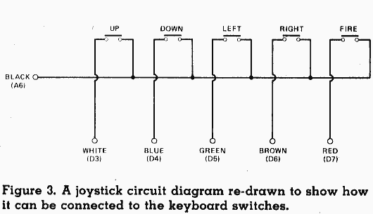
So, you can wire up the joystick so that it duplicates the effect of
those five keys. Any program which uses the direction keys can now be
controlled using the joystick, and Table 1 indicates some of the
programs which may be used in this way.
Table 1. Programs compatible with
the joystick
| Scripsit |
Word Processor |
| Visicalc |
Spreadsheet |
| Pascal-80 |
Compiler/editor |
Plus most other word-processors and program editors.
Dozens of games, including Robot Attack, Gobbleman, Asylum,
Meteor Mission, Space-Vaders, Penetrator, Starfighter,
Voyage of the
Valkyrie, Starfighter, U-Boat, Attack Force, Defend,
Firebird...!
Wiring Up A Joystick
We have shown that it is possible to connect a Genie and a standard
joystick together, but how are the actual connections made? At this
point it should be said that a joystick modification will involve some
small-scale rewiring inside your computer. This will invalidate the
warranty, so don't attempt this unless you have some experience of
electronics. However the mod requires only six soldered joints to be
made, and no sensitive components are affected, so it is' not a very
demanding project. The procedure is explained in very great detail to
minimise the chance of mistakes.
You can buy a standard joystick for about £6 from most shops
which sell computers or video games. They are marketed as add-ons for
Atari and Vic computers, but they are ideal for the Genie if a few
simple modifications are made. Note that the joysticks used on
computers such as the BBC Micro and Dragon are not compatible with the
Genie - they generate a continuously-varying signal which cannot be
read without quite complicated hardware.
If you are a real arcade fanatic you could use one of the 'quality'
joysticks (these are also sold as Atari add-ons). They feature multiple
fire-buttons and smoother response than the 'standard' sticks, but they
cost more than twice as much. Quality joysticks are generally only
available from specialist computer shops. Trade names include 'Point
Master', 'Le Stick' and 'Command Control'.
The Making of Mice
If you want to build your own joystick you will need to be fairly
skilled at construction - it can be rather annoying to have your
home-made masterpiece collapse in ruins just as you're about to set a
new high-score! If you decide to spurn Atari all you will need, besides
patience and a steady hand, is five fairly sturdy momentary-action
switches, a small box and some connecting wire.
Figure 4 shows how you can build a 'mouse' type joystick. The box rests
on the four direction switches with the fire button projecting from the
top of the box. The rubber foot at the centre of the base of the box
makes it impossible for the user to select all four directions at once.
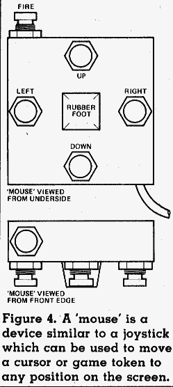
The size of the box you use is not crucial, but it should obviously be
small enough to fit comfortably in your hand. The position of the fire
button is really a matter of personal preference - you may find it best
to fit it on the front surface of the box, where you can work it with
your finger, or on one side where your thumb can reach it. Finally, if
you are feeling silly enough, you can cover the whole thing with
fur-fabric or knit a mouse-cosy!
Getting Hooked
Whether you build or buy your joystick, you will need a few tools to
fit the modification. You'll need a soldering iron of 25 watts or less,
some solder and a cross-point screwdriver. If you want to do things
properly it would be a good idea to buy a plug and a socket so that you
don't end up with the joystick permanently fixed to your computer. The
Atari joystick plug is rather an odd one, so we chopped it off and
fitted a DIN plug in its place.
If you remove the joystick plug you will find six wires inside. Table 2
indicates the colour-code used. These colours are more-or-less standard
for the PET and Atari joysticks, although red, orange or pink may be
used for the 'fire' button. If you are in any doubt about the colour
code then it is quite easy to check it by dismantling the joystick - it
is not difficult to trace the wiring.
Table 2. Joystick colour-code.
| BLACK |
Common wire. |
Terminal 2. |
| BLUE |
Joystick down. |
Terminal 20. |
| BROWN |
Joystick right. |
Terminal 19. |
| GREEN |
Joystick left. |
Terminal 16. |
| ORANGE/RED |
Fire button. |
Terminal 17. |
| WHITE |
Joystick up. |
Terminal 18. |
There are six wires, so the obvious choice of connector is a 7-pin DIN
plug. Unfortunately it is rather difficult to find 7-pin chassis
sockets, so we decided to use a 5-pin plug. Five wires are connected to
the pins of the plug and the sixth goes to the 'screen' around the
outside of the plug. So long as you use a metal DIN socket, you can
pick up the signal from the screen by connecting the appropriate wire
to the frame of the socket.
Another acceptable approach is to use two stereo jack plugs and sockets
to convey the six signals: three on each plug. The advantage of this
scheme is that it is much easier to solder to jack plugs and sockets
than to DIN connectors there isn't much room for error inside a DIN
plug!
First Peel Your Genie
Fit the chosen plug to the end of the joystick lead, pull out all plugs
connecting the computer to anything, and then dismantle the Genie.
Figure 5 shows the position of the eight screws which must be undone
before the top can be removed: don't undo any other screws or the
computer's power supply will fall out!
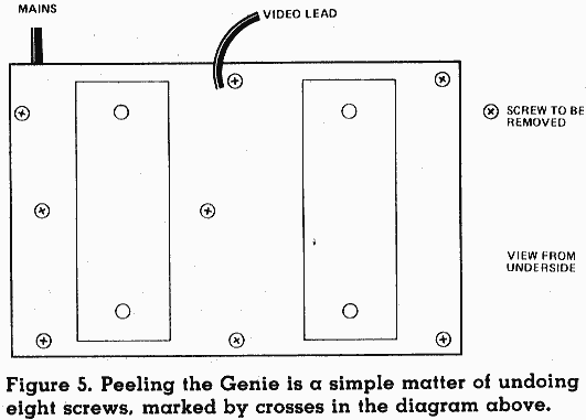
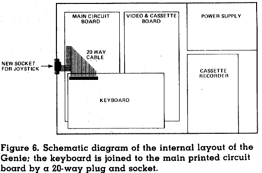
Figure 6 shows the inside view of the computer. Disconnect the 20 way
cable which joins the keyboard to the main circuit-board on the
left-hand side of the machine. The cable can be detached from the
socket on the keyboard, but be careful to pull gently and evenly so
that you don't bend the wines at the end of the cable. Now you have
electrically isolated the keyboard from the rest of the machine.
Eight screws around the perimeter of the board hold it in place; undo
them and lift the keyboard assembly out of the computer. At this point
the socket for the joystick can be fitted. Figure 6 shows the position
of this; it is mounted in the lower part of the box, just below and to
one side of the main circuit-board.
Six wires will run from this socket (ideally via another plug and
socket pair) to the -keyboard assembly. Figure 7 shows where you should
connect the wires to the keyboard.
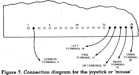
Turn the keyboard assembly so that the keys face downwards and the
space bar is furthest from you. At the left-hand side of the closest
edge of the board is a row of twenty terminals, and on the other side
of the board these connect to the 20-way socket. Solder the six wires
from the joystick socket to appropriate terminals on the row, using
Figure 7 as a guide. Table 2 indicates which wire goes to which
terminal, assuming that the terminals are numbered 1-20 from left to
right (the Revision B Video Genie circuit board actually labels the
terminals in this way).
When you solder the wires take care not to bridge the gaps between
terminals. If you do accidentally do this you will have to remove the
'bridge' of solder, or the computer won't be able to distinguish
between keys properly. The terminals are not directly connected to any
sensitive electronics, but you should still avoid heating up any
terminal for longer than a few seconds at a time, or you may damage the
socket on the other side of the circuit-board.
If you have a later model Genie I computer with four arrow keys rather
than the original ESC and CTRL keys you may find that the keyboard
circuit board in your computer contains a set of un-used pads. These
are intended for the numeric keypad added for the Genie II, but include
all the same signals needed for the joystick. You may find it more
convenient to make the new connections there, tracing connectivity from
the locations shown in Figure 7 to the new pads, near the middle of the
computer.
Another idea that has come up since the original article was written is
that you may wish to leave the plug on the joystick and fit a 9 pin
male D-type connector in the computer. As well as the Atari and Vic
joysticks mentioned in 1983 you will find that keypads and joysticks
made for Sega Megadrive, MSX, Commodore 64 and Amiga systems use a
compatible circuit - unlike controllers made for Sony or other
consoles, or the 15 pin and USB ones used on Apple and IBM-compatible
PCs, or those for Dragon, Tandy Color Computer or BBC micro systems;
those are not compatible with this circuit as they use analogue or
serial rather than digital parallel signals.
Once all of the wires are safely connected you may re-assemble the
computer, but before you do so you should look closely at all of the
work you have done - make one final check of all of the connections.
Screw the keyboard assembly back in place, taking care not to do the
screws up too tightly, since they bore directly into the plastic
pillars of the box. Re-connect the 20-way cable between the main
circuit board and the keyboard.
The trick here is to make sure that all of the wires are straight
before you insert them and push them all into the socket at once,
evenly. Don't force the wires - if they are reluctant to go in then
pull them back, straighten them, and try again. Be careful not to plug
in the cable out-of-step one place to the left or right of the correct
position. It is easy to make a mistake and 'miss' with one wire, so
that it does not enter the socket. Look above and below the socket to
make sure that no wires have gone astray!
The last step is to close the computer case. Put the lid back and
replace the eight screws which hold it in place. The shortest of these
screws goes into the hole nearest to the mains-lead; the positions of
the other screws are interchangeable.
A Trying Time
If all has gone well, you should have a working joystick modification.
This project has been successfully carried out by many digital disaster
areas, including some people who have trouble wiring a 13 amp plug the
same way twice, so your joystick should work perfectly. However it is
best to test the modification systematically.
Plug in your computer and TV, but don't connect the joystick yet.
Likewise, if you've got a disk system then leave it disconnected. It is
very unlikely that you will have done something wildly wrong, but it is
best to connect up the minimum of hardware just in case.
When you power up the computer it should work as normal. If the usual
display does not appear then you have accidentally altered the workings
of the computer. No one who has fitted the modification so far has had
this problem, so award yourself ten marks for ingenuity, then unplug
the computer immediately and check all of the connections you made.
You may find that the display appears as normal but the keyboard does
not work. If the red power light is not glowing then you have plugged
in the 20-way cable wrongly. Likewise if some keys do not appear to
work you may have fitted the cable in the wrong manner. Unplug the
computer and check the position of the cable. It is very unlikely that
you have damaged the computer in any way.
You might find that some keys generate the wrong codes - 'J' and 'R'
might both produce the 'R' character, for example. If this has happened
then you have accidentally shorted out some of the keyboard
connections. Don't worry, this will not harm the machine but it will
make it rather difficult to type programs until you cure the problem!
Unplug your computer and check the wiring on the underside of the
20-way connector, looking for solder 'bridges' between the terminals.
If you can't see any it may be that wires on the joystick socket are
shorting together. Re-solder the wires so that they can't accidentally
touch one another.
If all of the keys on your machine seem to work correctly then load
Program 1. Connect up the joystick, and when you push the joystick
forwards the message "UP" should appear. Likewise the fire button
should produce "BANG" and the other directions should work sensibly.
Make sure that you can generate 'diagonal' signals - it should be
possible to produce "UP" and "LEFT" simultaneously by pushing the
joystick away and to the left.
At this point you may find that some joystick directions don't
register: this means that the connection between the joystick and the
keyboard is not complete. First check the plug on the joystick lead. If
that looks correct then dismantle the computer and ensure that the
wires between the socket and the keyboard are intact and correctly
placed.
The joystick may create multiple signals even when you only move it up,
down, left or right. In this case there is a short circuit in the plug
at the end of the joystick lead (a short inside the computer would stop
the keys working properly).
There is one more possible problem. It might be that all of the
directions produce a unique signal but you get the wrong message for a
given direction. Perhaps "LEFT" appears when you move the stick right.
You can correct this in a number of ways, but the easiest is probably
to change the wiring inside the joystick. A standard Vic or Atari
joystick will contain clips connecting coloured wires to the internal
switches so you can swop over colours by exchanging the clips,
Alternatively, swop over the soldered wires in the plug or inside the
computer.
Conclusion
By now you should have full arcade-style joystick facilities on your
Video Genie. At last you can look Atari owners straight in the eye.
Just centre them in your Space Gunsights and press the 'fire' button...
Simon N Goodwin, simon (at) studio (dot) woden (dot) com


